In an earlier post our experience of adding a uBlox GPS receiver directly onto the PCB of the iC880A, and commented that whilst it was doable it required a tricky soldering, even with the most challenging component needing to be omitted, so we looked into ways of adding a GPS module without needed surface mount soldering skills.
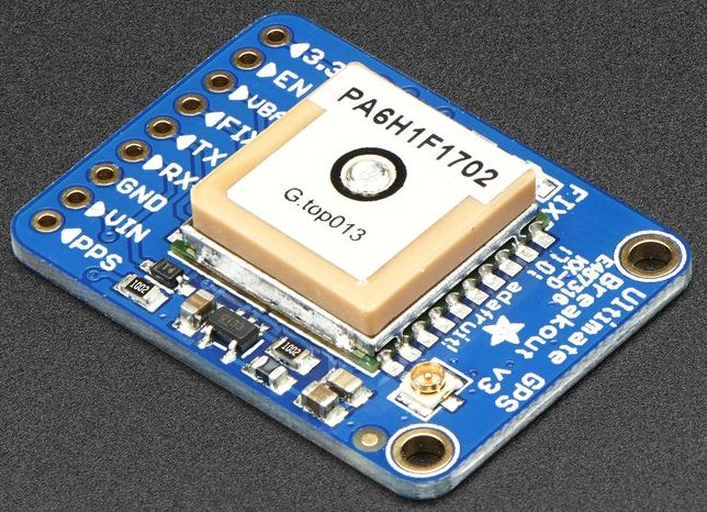
We had recently been looking at GPS receivers for another area of a project being worked on and decided to use the Adafruit Ultimate GPS. The reasons we liked the module were the fact it could take an external antenna, and it offers a PPS output. The external antenna is important because all our LoRaWAN base stations use metal enclosures. The PPS output means it can be used in place of the uBlox. The PPS (Pulse Per Second) output is a output pin from the GPS receiver which is used to signify the start of the second. By using a simple output rather than a character over a serial link a much higher accuracy can be achieved, as much less hardware processing is needed

In order to connect this to the iC880 a standard 0.1″ header was soldered onto the GPS module. As this was just for testing the serial port is connected to the Raspberry Pi using a standard FTDI USB-serial converter cable. For the power, ground and PPS connectors our much abused Raspberry PI iC880A Lora Concentrator Gateway Shield has had some more patch wires soldered onto it, this time with sockets on the end to enable plugging into the 0.1″ header on the GPS module.
Software
    "gateway_conf": {
    "gateway_ID": "B827EBFFFEXXXXXX",
    "servers": [
        {
            "server_address": "router.eu.thethings.network",
            "serv_port_up": 1700,
            "serv_port_down": 1700,
            "serv_enabled": true
        }
    ],
    "gps_tty_path": "/dev/ttyUSB0",
    "contact_email": "test@example.com",
    "description": "GPS-test-node",
    "fake_gps": false,
    "forward_crc_valid": true,
    "forward_crc_error": false,
    "forward_crc_disabled": true
    }
}
The local config is very similar to that used for the uBlox module the only change is the serial port being used.
Testing
As before testing had to wait until with weather co-operated. When started up the program went through the same steps as seen last time waiting for the GPS receiver to send the correct data through before using it for a lock. This is still attempting to send beacons out, however this time it is succeeding. Although this could be because it’s connected to a different concentrator board.
NOTE: [down] beacon ready to send (frequency 0 Hz)
--- Beacon payload ---
0xEE - 0xFF - 0xC0 - 0x00 - 0x00 - 0x00 - 0x00 - 0x84
0x00 - 0x00 - 0x9F - 0x91 - 0x59 - 0x38 - 0x0E - 0x1C
0x8C - 0x00 - 0x00 - 0x00 - 0x00 - 0x00 - 0x00 - 0x00
--- end of payload ---
NOTE: [down] beacon sent successfully
I am still confused as to why it is sending out beacons given it again clearly says
INFO: Beacon is disabled
Maybe I’m misunderstanding what this configuration option means.
At the moment we have just tested that the gateways are getting the time / position from the GPS receiver, we are not doing anything more advanced with it. That will come in time, and updates will be posted.
So glad I came across these 880 posts. Thanks for sharing and bringing back memories of Burgess Road – I was at Soton University back in the ’70s. Happy days!